English
 中文
中文How a Visual Positioning System Improves Case Making Accuracy
 Jul 13,2026
In hardcover case making, the difference between a premium product and a rejected piece often comes down to a fraction of a millimetre. When a printed cover sheet is glued and wrapped around grey board, even a 0.5 mm misalignment between the cover graphics and the board edge creates a visible defect—a crooked spine, an off-centre title, or an uneven border margin that the end customer notices immediately. On a manual or semi-automatic line, maintaining consistent alignment across hundreds of cases per shift depends almost entirely on the operator's skill and attention span. A modern Case Making Machine equipped with visual positioning technology changes that equation, replacing operator-dependent placement with automated, camera-guided correction that delivers consistent accuracy from the first case of the morning to the last case of the night shift.
How Manual and Semi-Automatic Gluing Falls Short
In a conventional case-making workflow, the operator places the printed cover sheet onto the gluing table or feeds it into a roller coater. The sheet then moves to a positioning station where the grey board is manually aligned against guide marks or registration pins. The operator checks the alignment, adjusts if necessary, and proceeds to edge folding. This process has three inherent weaknesses.
First, placement accuracy drifts as the operator fatigues across an eight-hour shift. Second, printed sheets with dark backgrounds or subtle registration marks are difficult to align under standard factory lighting. Third, any variation in the die-cutting of the grey board—which can deviate by 0.2 mm to 0.3 mm between batches—requires constant micro-adjustments that are impractical to maintain manually. The result is a rejection rate that climbs throughout the day, peaking on the last shift before the weekend.
How a Visual Positioning System Works
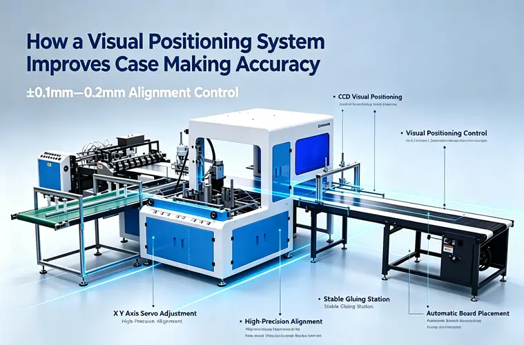
A visual positioning system replaces the manual placement step with an automated alignment process driven by a CCD camera. The sequence works as follows: the printed cover sheet is placed on the infeed table and conveyed to the positioning station. A CCD camera mounted above the station captures an image of the cover sheet. The system's software identifies pre-programmed registration marks or, in more advanced systems, detects the edges of the printed graphics themselves. It then calculates the precise coordinates where the grey board should be placed to achieve perfect alignment.
The grey board arrives at the station on a separate track. Small servo-driven adjustments shift the board's position in both X and Y axes—and, in some systems, rotate it slightly—to match the calculated placement point. Once aligned, the board is pressed onto the glued cover sheet. The entire process—capture, calculate, correct, and place—completes in under a second, maintaining the cycle speed of the surrounding production line.
Why Camera-Based Positioning Outperforms Mechanical Guides
Mechanical guides and registration pins work on the assumption that every grey board and every cover sheet are dimensionally identical. They are not. Paper stock expands and contracts with ambient humidity, and grey board edges are rarely perfectly square after die-cutting—a slight angle of even 0.1 degrees across a 300 mm board creates a visible skew at the corner of the finished case.
A camera-based system does not reference the board edge against a mechanical stop. It references the printed image on the cover sheet—the only thing the end customer sees. This shift in reference point means that the system compensates for minor variations in both the grey board and the cover sheet simultaneously. The alignment accuracy improves from a typical manual tolerance of ±0.5 mm to a camera-guided tolerance of ±0.1 mm to ±0.2 mm. For short-run, high-value work such as limited-edition book covers, presentation boxes, or luxury packaging, this tighter tolerance is the difference between first-pass yield and costly rework.
The Role of Image Processing Software
The camera hardware is only one part of the system. The image processing software determines how reliably the machine performs across different cover designs. Three software capabilities matter in daily production.
First, multi-point registration allows the system to register against multiple marks or graphic features simultaneously. This is essential for large-format covers where a single registration point near one corner leaves the far edge unverified. Second, pattern-matching algorithms can detect alignment features on dark, textured, or metallic substrates that would confuse simpler contrast-based systems. For converters working with a wide range of cover materials, exploring gluing and positioning equipment with advanced software capabilities can help assess whether the image processing system handles the full spectrum of substrates in your product line. Third, auto-teach functions allow operators to program a new cover layout by placing a single sample in the correct position and pressing a button—the system learns the pattern and applies it to the entire production run.
Key Specs When Evaluating a Visual Positioning System
When comparing visual positioning systems across different manufacturers, several specifications indicate real-world performance. Positioning accuracy, typically stated as ±0.1 mm to ±0.2 mm, should be verified with the actual cover stock and grey board you intend to use—not just a manufacturer's standard test sheet. Cycle time for the capture-and-correct sequence must stay within the upstream glueing speed; if the gluer runs at 26 pieces per minute, the camera system must complete its correction in under 2.3 seconds to avoid becoming the bottleneck.
Lighting integration matters more than pixel count. A camera system with integrated LED illumination delivers consistent image quality regardless of ambient factory lighting. Systems that rely on ambient light perform inconsistently as the overhead lights age or shift with the seasons. The camera resolution, typically 2 to 5 megapixels for case making applications, provides sufficient detail for sub-millimetre edge detection without generating unnecessarily large image files that slow processing.
Reducing Glue Waste Through Precision Placement
An often-overlooked benefit of camera-guided positioning is glue waste reduction. When a cover sheet is placed manually and the board is misaligned, the operator typically discards both the cover sheet and the board—the glue has already been applied. The cover sheet carries printed graphics, coatings, and sometimes foil stamping, making it the most expensive component in the case-making process. Reducing the rejection rate from, for example, 5% to below 1% through consistent automated alignment cuts material waste proportionally. For a line producing 5,000 cases per shift, a 4% reduction in cover sheet waste represents hundreds of saved sheets per day.
Evaluating Payback on a Visual Positioning System
The decision to invest in automated visual positioning balances three factors: current rejection rates, labour cost for rework, and the value of the raw materials being discarded. A line running high-cost metallic or textured cover stocks recovers the investment faster than one running standard printed paper. The calculation is straightforward: multiply the daily rejected cover count by the per-sheet cost, then add the labour hours spent on inspection and rework. For most luxury packaging operations, the payback period falls within 12 to 18 months of single-shift operation.
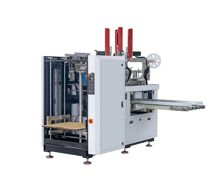
For packaging converters seeking equipment that integrates these capabilities, JUXIN's case-making equipment with visual positioning supports a range of finished sizes and dual-purpose box/case configurations. Requesting detailed specifications tailored to your specific cover materials and production targets is a practical next step toward evaluating whether the technology fits your operation.